Planar Structures and Fluid Salients
THE STRUCTURING OF MOVING FLUIDS
Fluid Salients and Planar Structures
(The Structuring of Moving Fluids) [8]
Michael A. Gorycki, Ph.D. (Revised June 26, 2018)
ABSTRACT
The importance of fluid salients to the structuring of moving fluids in a number of natural and laboratory phenomena has been discussed in several of my web sites. Included in the present web site are additional comments on some subjects already discussed, as well as simple experiments, observations, and/or arguments for additional phenomena. I believe these involve the mechanism of fluid salient formation in what are here essentially two dimensional configurations that present as planer structures. These additional structures include: Taylor-Couette flow, Langmuir Circulation, current ripples and drag folds, rainbands, cloud rows, plunging waves, the circulation of Jupiter’s atmosphere, density currents, haboobs, weir draperies, tornado swarms, plate tectonics, two-dimensional combustion fingerings, clear air turbulence, and what I call ablative snow striae. Doubtless, there are still other examples of the fluid salient mechanism to be recognized.
The general structure of a fluid salient series and the shape that each salient exhibits in that series can vary. Both depend on the environment of their formation. As a result of this and the diverse nature of the phenomena described here and in my other web sites, it can be seen that the mechanism presents in a variety of aspects. As a consequence, the arguments presented suggest that fluid salient formation is a unifying mechanism in the structuring of any moving fluid, and appears to be active between laminar and turbulent flow when a critical velocity has been attained.
INTRODUCTION
As described in this and my other web sites,
[1] Fluid Salients and the Structuring of Moving Fluids
[2] Fluid Salients and the Formation of Beach Cusps
[3] Fluid Salients and Spiral Galaxies and Other Vortices
[4] Fluid Salients and the Formation of Round Phenomena
[5] Fluid Salients and Linear Structures
[6] Fluid Salients and Stream Meandering
[7] Fluid Salients and the Jet Stream
[8] Fluid Salients and Planar Structures
a large number of seemingly disparate natural and man-made phenomena may be explained by the operation of a simple, easily observed and readily understood mechanism which I call fluid salient formation. This is the production of evenly spaced salients, and intervening zones of retarded-reversed flow, that are formed during the movement of fluids. It is caused by the attainment of a velocity sufficient to produce them, resulting in the extension and consequential compression of the fluid’s structure, and is the product of either shearing and/or overrolling. Extension/compression is an easily described and demonstrated mechanism that is applicable to any planar periodicity. I would additionally suggest that turbulence can develop as a consequence of the deterioration of the fluid salient structuring if the flow regime exceeds a certain size and speed. That is, fluid salient structuring can be both a forerunner to, and be responsible for, turbulence. Once turbulence develops, the structuring of laminar flow and fluid salients is lost.
I also suggested in my earlier web sites that fluid salients are ubiquitous and legion, and that the list presented of phenomena generated by the operation of fluid salient formation was likely incomplete. Following are several I would like to add to the list along with some already described that require additional comments. All represent planar fluid salient formation. I feel that a planar mechanism is also in operation for the production of beach cusps but these are discussed in detail elsewhere, [1], [2]. As a conceit, a number of asides have been included in the discussions of the various phenomena. It is hoped they add to the argument.
LIST OF PHENOMENA INVOLVING PLANAR FLUID SALIENT FORMATION
Current Ripples and Drag Folds
Langmuir Circulation
Density Currents
Taylor-Couette Flow
Cloud Rows
Jupiter’s Atmospheric Taylor-Couette Vortices
Plunging Waves
Rainbands
Haboobs
Weir Draperies
Evenly Spaced Icicles on a Wire
Tornado Swarms
Plate Tectonics
Two-Dimensional Combustion Fingerings
Hele-Shaw Cells
Clear Air Turbulence
Ablative Snow Striae: Sastrugi
Current Ripples and Drag Folds
It is suggested here that current ripples in sand, water, air, or drag folds in a layer of solid rock (acting as a “fluid sheet”) become structured through shearing, and might be considered another version of the fluid salient mechanism since they are evenly spaced, are of the same size, and have alternating zones of retarded flow. It would be remiss not to suggest that the hot melt model (fugitive hot glue adhesive) seen here in Figs. 1 and 2 is also composed of drag folds representing shear structuring.


Fig. 1a. (top) A 60 by 3 by 0.5 mm rectangular strip of fugitive hot melt adhesive resting on and pressed between clean, unlubricated plate glass surfaces. The strip was cut and removed from a film produced by gently melting (using adequate ventilation), and cooling the adhesive between spaced, plate glass sheets. The upper plate has been translated to the left in a direction parallel to the long axis of the strip that rests on the lower glass sheet. Note the periodic rolls, which have increased in volume and width at the expense of intervening regions, due to Couette distortion of the strip. The model represents shear structuring of a moving fluid above a substrate. The rolls suggest depressed locations between elongate ridges in the structure and could be the cause of ripples in sand, water, mackerel sky altocumulus clouds, drag folds in rock, or evenly spaced rain bands. The left side of each bleb overrolls the neck to its left. The right side of each bleb is overrolled by the neck to its right. See also Fig. 6 [5].
Fig. 1b. (bottom) Enlargement of the upper figure showing at least 4 periodic rolls and the shadows they cast on a lower surface.
Drag folds are described as “minor folds that form in an incompetent bed when the competent beds on either side of it move in such a way as to subject it to a couple.” (Glossary of Geology and Related Sciences, 1957, p. 87). The motivating energy for the smoke ripples seen in [5] is shearing of smoke between fast and slow-moving air within the smoke plume; for the hot melt model it is shearing between two glass plates.
Comparing the hot melt model to the rubber cylinder model (Fig. 2),


Fig. 2a and 2b. Two similar images of the unlubricated rubber cylinder model. Motion of upper glass plate parallel to the axis of the cylinder, especially in the figure on the right. Note the blebs which are analogous to the rolls in the strip of the fugitive hot melt adhesive in Fig. 1. In both, the deformable material tries to expand axially, but, because of coupling (overrolling), is repeatedly deformed over short, evenly spaced distances. The spacing of blebs depends, at least, on the nature, thickness, and width of the material, and pressures exerted. They are in a straight line because lubrication was not used (see Fig. 9 [6].
the location of the two ends of the rubber cylinder, either at rest or deformed, is unchanged if a lubricating oil is not employed (see Figs. 8-9 [6].
The unlubricated cylinder (Fig. 2) produces evenly spaced blebs (waves) which become flattened by the glass plates. Both models (Figs. 1a, 1b, 2a, 2b) not only exhibit the periodic spacing of sand and water ripples, but exhibit appropriate growth along the length of the ripples in a direction perpendicular to what would be the wind direction. Note that there is no growth between the blebs or rolls, a position occupied by the zone of retarded-reversed flow. This is a further confirmation of the fluid salient mechanism being responsible for the production of drag folds (couples). The term drag fold is merely descriptive. The term fluid salients defines the mechanism responsible for their production. Also, sinuous ripples, giving way to linguoid ripples, might owe their more complex forms to a simultaneous compression of the drag folds at right angles to the mechanism responsible for the primary ripple structure. This secondary rippling, at right angles to the periodic rolls of the fugitive hot melt adhesive (Figs. 1a and 1b) and the rubber blebs (Fig. 2a and 2b), is not seen here because they are not long enough to experience extension/compression in a direction at right angles to the length of the strip or cylinder.
In the lubricated model, (Fig. 3)

Fig. 3. Lubricated rubber cylinder model similar to Fig. 2. Here, the direction of motion of the upper glass plate is again parallel to the axis of the cylinder and leads to the extension and repeated deformation relieved by development of sinuosity, and an overrolling of both sets of limbs of the sinuous curves (see Fig. 9 [6]).
the deformation of the cylinder is relieved by the development of periodic sinuous curves which relieve the elongation suffered by the cylinder. The curves alternate in direction similar to stream meandering [6], but their spacing, again, depends, at least, on the nature, thickness and width of the material, and pressures exerted.
As an aside, Bagnold's (1941) suggestion that saltation paths for grains of a given size allow for the formation of evenly spaced ripples in cross-section, but this two-dimensional representation fails in the third dimension; i.e., along the length of the ripples. That is, why should saltation sites be in register along the length of a ripple unless there is a structuring to the air (overrolling) in the ripple trough, aligned and extending parallel to the ripple length? The point to be made here is that structuring of the air apparently antecedes and causes structuring of the sediment.
Further, evenly spaced, parallel, ocean waves that approach a straight beach (Fig. 3a), either under or far from a driving wind, likewise seem to be the result of drag folding (planar fluid salients), (Figs. 1a and 1b) because the overrolling waves are constrained between the wind and the sea bottom.
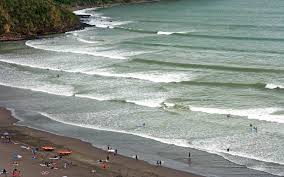
Fig 3a. Waves approaching a beach are usually evenly spaced, are of the same size (see Fig. 1a), and are the result of the fluid salient mechanism.
They are not constrained laterally which would cause extension/compression, but are allowed to spread and increase their lengths to some extent, at right angles to their direction of motion. Overrolling can best be seen when a plunging breaker steepens (because of friction with the bottom), curls, and drops onto its own trough (the zone of retarded flow). Of importance, waves breaking on a straight beach face tend to be parallel to it as they approach, and are rather straight because of the influence of the bottom’s topography. It has been suggested (Munk and Traylor, 1947) that both underwater topography and beach erosion is altered by incoming waves.
I suggest that a causative factor for this phenomenon on straight beaches may be demonstrated with the help of the following physical model: place a thin copper wire (250 microns thick) on a flat sheet of plywood. Cover it with a second sheet of plywood and, pressing down, roll the wire, back and forth, between the two sheets. In a short while the wire will become almost perfectly straight (collinear), even if it originally exhibited a number of gentle bends. This is due to the copper’s malleability as well as the flatness of the sheets and the pressure they exert. Also, the wire is nonelastic when compared to the rubber cylinder in Fig. 3 and cannot produce fluid salients. In the model, the wire is the overrolling wave, the wire’s axis is perpendicular to the direction of rolling of the wave orbit, the lower sheet represents the beach face extending to the wave base where the wave orbit begins to “feel bottom”, the upper sheet represents the energy produced by the force of the wind and the effect of gravity. The most likely source of these waves that approach parallel to the shoreline are sea breezes which approach perpendicular to the shore, “are more localized than prevailing winds”, and are “a common occurrence along coasts after sunrise.” (see Sea breeze-Wikipedia). They are analogous to Runoff Wave trains, seen on driveways [5], which are driven by gravity. The purpose of this physical model is to accent the effect that this orienting mechanism has as a precursor on the formation of planar fluid salients, including evenly spaced Langmuir Circulation, the structure exhibited by density currents, and the conditions conducive to beach cusp formation as waves reach the shore and lateral extension operates.
I also suggest that wave refraction is in response to a wave front approaching the beach at an angle. When the wave begins to feel bottom, it becomes oriented parallel to the beach, much like the orientation of the copper wire physical model’s orientation to the direction of rolling. Both sea breeze and refracted waves would also have a reciprocal influence on the bottom’s topography.
Langmuir Circulation
An argument can be raised with regard to Langmuir circulation. Langmuir (1938) noticed that on the ocean’s surface, narrow streaks of floating seaweed with broad interstreak areas, were arranged in lines parallel to the wind direction. Measurements made elsewhere by Langmuir showed descending currents below the streaks with ascending currents in between.
Experimenting on Lake George, New York, Langmuir placed a white cord on the water’s surface perpendicular to the wind direction. To make the cord float he attached small fragments of cork. “After 10 min this cord had developed well-defined waves, being displaced forward in the direction of the wind in the streaks and backward in the spaces between them, indicating that the forward velocity of the water was greater in the streaks than in the spaces between them. The water rising from deeper levels has a low forward velocity, but this increases steadily through the action of the wind so that when the water reaches the streaks it has the maximum velocity.” (Langmuir, 1938).
Quoting from “Langmuir Circulation Cells” [1], I stated, if “wind salients (are) centered on the broad inter-streak areas, they would push surface water and debris bilaterally and downwind toward the streaks and expose relatively still subsurface water underneath the salients. Since the debris would present a frictional drag on the wind, the wind would also preferentially move the streak areas more quickly downwind compared to the upwelling water in intervening areas, which would initially have comparatively little of a down-wind component to its motion.” That is, Langmuir proposes that his floating corks suggest a fast water speed over the streaks, and slow water speed over the zones of divergence, but did not consider the wind speed in the inter-streak areas. This last comment is supported by the fact that Langmuir had to wait “10 min” for the floating corks to arrange themselves into “well-defined waves” because there is really a slow wind speed over the windrows, along with a very slow water speed over the intervening areas of divergence.
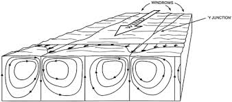
Again, I suggest that it in keeping with the fluid salient mechanism the wind in the broad zones of divergence is flowing more quickly as active salients than the passive wind over the narrow zones of retarded flow where the streaks (or windrows) are located. That is, if the wind was fast over the streaks (as in Fig. 4),

Fig. 4. Other workers supposed Langmuir circulation at depth and wind velocities at the surface. The cross-section shown is in opposition to Langmuir’s observations that circulation of the water occurs only at shallow levels. The windrows shown are narrow zones of convergence where seaweed, debris and foam accumulate. Wind velocities at the surface (heavy arrows) are shown here to be greatest over the windrows and lowest over the zones of divergence. As discussed above, it is really slow-moving wind over the windrows that permits the accumulation of debris caused by the fast-moving wind over the zones of divergence. It is also the reason that; accumulating surface water descends beneath the streaks, newly exposed near-surface water rises at the zones of divergence, and the divergent surface water is slow moving. Water, rising from depth, is newly exposed to the force of the wind and is initially slow-moving. Salient formation is suggested by the broad width to the evenly spaced areas of divergence caused by the strong wind flow which sweeps debris and surface water to the narrow windrows of convergence.
then the debris would disperse and deeper water would migrate up to the surface. Also, if the wind were slower over the inter-streak areas, the debris would accumulate there and the surface water would sink.
Some workers suggest that in Langmuir circulation, an unstructured wind suffers spanwise “perturbations” that creates the evenly spaced, paired counterrotating vertical vortices at the water’s surface. These vortices become stretched into horizontal counterrotating vortices at the water’s surface because of wind flow, and these are responsible for the upward and downward vertical flow (see Langmuir circulation, Wikipedia). As a consequence, the vortices must precede the formation of the streaks.
I contend in my earlier web site [1], that it is the initial active structuring (the evenly spaced fluid salients within the wind above the water surface) that actively produces the so-called Langmuir circulation cells. The structuring of the water is passively formed with only the surface and near-surface water being affected by a lateral spreading over the areas of divergence and a lateral convergence over the windrows. It is assumed by other workers that deeper water is actively involved in the supposed circulation cells’ structuring. As stated, Langmuir himself spoke against the presence of that circulation in the deeper layers which also does not have much effect at the base of the mixed layer. The fluid salient mechanism obviates the necessity for the sequence; perturbations, vertical followed by horizontal vortices, deep water involvement, and streak formation. (see Beach Cusps [2] for a discussion of perturbations or instabilities).
I feel that Langmuir circulation is a misnomer, and that the windrows should be called Langmuir streaks or salients due to the lack of counterrotating horizontal vortices extending into deeper water. I consider the structuring of the water to be the result of active overrolling of the leading edge of the overlying air, the development of extension/compression along that overrolling, the resultant production of evenly spaced broad fluid salients, and the intervening narrow zones of retarded flow over the streaks (see Beach Cusps [2].
As an aside, wind-blown snow on highway surfaces usually forms small patches of Langmuir-like patterns which, obviously, are generated within the transparent air above the pavement. The same holds for longitudinal and parabolic dunes (see below) caused by the invisible structuring of the wind (fluid salients) above the sand. Fluid salients in moving air, with their evenly spaced periodicity, can be the cause of a variety of dune shapes, especially if there is a variation in the amount of sand available for each dune type.
Density Currents
The elongate structure of subaqueous density and gravity currents depicted in my earlier web site is similar to the rubber cylinder physical model presented as the mechanism for the formation of beach cusps (see Fig. 2 in [2]), because of the formation of fluid salients at the leading edge, and intervening elongate zones of retarded flow (Fig. 5).

Fig. 5. Evenly spaced salients seen at the leading edge of a density current produced by a colored, saturated salt solution moving beneath standing water. The production of the salients gives rise to the elongate zones of retarded flow, extending upstream, on either side of each salient. The motivating force is gravity which causes the current to overroll at its leading edge to form the fluid salients and intervening zones of retarded flow.
A number of workers have remarked on density currents; (Allen, 1971), (Komar, 1972) and (Simpson, 1972), but little is said about the reason for the formation of evenly spaced lobes (salients) and associated clefts and tunnels (zones of retarded flow) on either side. There is also no indication of (or reason for) paired evenly spaced vertical or horizontal counterrotating vortices as suggested by workers for Langmuir circulation cells. Simpson (1972, Fig. 7) does show shadowgraphs of “lobes” and “clefts” at the head of a density current, which I would call fluid salients and intervening zones of retarded flow. Allen (1971, Fig. 3) also presents a sketch of “fingers” and “tunnels”. To explain their formation Allen describes “the operation of a current in which the bed shear stresses exerted by the flow varied transversely across the current with a certain spatial periodicity.” This “spatial periodicity” is similar to the “perturbations” called upon to explain the even spacing of Langmuir circulation cells. Simpson (1994) only implies the operation of a passive extension/compression of the fluid salient mechanism as depicted in his diagram below. He depicts a sea breeze front, with cold air overrunning warm resulting in an “instability” leading to the formation of the clefts and lobes (Fig. 6), but he does not elaborate on their formation or their even-spacing. This diagram of a backward overrolling sea breeze front does not conflict with the fluid salient mechanism. However, his bifurcating axial arrows are associated with the cleft, when I would suggest they should be the cause of lobe formation due extension/compression in keeping with the fluid salient mechanism.

Fig. 6. Simpson’s (1994) diagram of the lobes and cleft in a sea breeze front.
My interest in density currents stems from a simple observation I made which led to the development of the fluid salient mechanism and my paper on the origin of beach cusps (Gorycki, M. A., 1973a). While sloshing a small amount of fresh water across the bottom of a 45 cm long, flat-bottomed tray I noticed that the leading edge of the produced wave simply formed a series of evenly spaced salients separated by nascent zones of retarded-reversed flow. McGee (1897), noted that “pure water”, flowing over an indestructible surface, does tend to divide into parallel streams which he calls sheetflood (Glossary of Geology and Related Sciences, 1957, p. 263). I would call this structuring, seen to extend tenuously upstream in Fig. 5, retarded zones, but McGee does not mention the evenly spaced salients that are seen at the leading edge. This observation leads to the conclusion that it is not the presence of any overlying standing water or a dense fluid phase that causes fluid salients, but that they depend only on the presence of fresh water moving down a slope (see Fig. 4 [2]. Thus, the flat-bottomed tray that I described is a more simple, easily observed physical model since there are there are no clefts and tunnels (elongate zones of retarded flow) extending upstream on either side of the salients.
Taylor-Couette Flow
I suggest that the conventional (established) structure of Langmuir circulation (Wikipedia, Images) relies heavily on the velocity profile of Taylor-Couette flow (Wikipedia, Images), and density currents, and that all three should be replaced by the fluid salient mechanism.

Figs. 7 and 8. Sketch of a Taylor-Couette device showing simple toroidals giving way to wavy toroidals with an increase in angular velocity of the inner cylinder. Three fluid salients (lobes) are depicted on the left side of the cross-section, each with a pair of counter-rotating edges (Taylor vortices) on the left.
The elongate structures seen in Fig. 5 are analogous to the Taylor-Couette structuring seen between two concentric glass cylinders. Fig. 11 shows the development of leading edge lobes (fluid salients) and tunnels (retarded zones). It would seem that the leading edge fluid salient front is not necessary for the development of toroidal vortices within the glass cylinders of the Taylor-Couette flow apparatus. This is because lateral extension/compression, so necessary at the advancing front of fluid salient flows is provided by and maintained at both ends (top and bottom) of the fluid annulus because the flow is not allowed to extend axially (vertically). That is, if the annulus is driven circumferentially by the faster rotation of the inner cylinder (a role taken by gravity and slope at the top of the gravity current), then there is everywhere a lateral extension of the fluid caused by the pressure differential of the faster moving inner layers of fluid in the annulus. This causes the production of large fluid salients next to the inner cylinder. It also causes the separations between the Taylor vortices, the smaller zones of retarded flow, and their separations at the surface of the outer glass cylinder (see the cross-section in the middle of Fig. 7 and 8). These zones may be made obvious by the presence of turbulence (and loss of reflectivity) when compared to a more laminar flow within the vortices, but even the vortices are subject to differences in reflectivity depending on their rotational direction. <A>
Because of restraints at the ends of the annulus, the Taylor vortices mechanism (fluid salients) develops over the annulus’s length without the necessity of leading edge lobes. Also, the salients can develop rectilinear cross-sections because of their growth and confinement between the glass cylinders.
Fluid salients are also produced by the wind which engenders the straight, lateral sides of parabolic dunes, Langmuir circulation streaks, as well as the gravity-produced density currents’ zones of retarded flow (Fig. 5), or Simpson’s (1972) clefts and tunnels in his shadowgraphs. All these structures, including salients, are formed by the faster moving portion of the fluid.
The rotation of the inner cylinder is the cause of the shear with the outer layers of fluid that generates the extension/compression. As suggested, this causes the production of the fluid salients and retarded zones in the Taylor device. If the rotation of the cylinder is progressively increased, the circular vortices become slightly tilted and must briefly deform into ellipses. This is quickly followed by seemingly more stable, wavy (sinuous) fluid salients, perpendicular to the axis of rotation, that eventually look to be meandering, followed eventually by turbulence. <B>
A simple physical model for this transition involves a small, vertical glass cylinder having, in this case, an inside diameter of 19 mm. If an O-ring having an outer diameter of 19 mm is inserted into the cylinder it will resemble a circular Taylor vortex. Repeat with an O-ring having an outer diameter 21 mm, and a tilted oval ellipse can be formed. Lastly, by pushing down on the higher vertex of an elliptical O-ring, with an outer diameter of 22 mm, to bring it to the same elevation of its lower vertex, a wavy “vortex” will form (perpendicular to the axis of the cylinder) similar to those produced by increasing the rotation of the Taylor-Couette device (Fig. 9).

Fig. 9. A vertical, thin-walled glass cylinder having an inside diameter of 19 mm. It represents the outer glass cylinder of the Taylor-Couette device. Near its bottom is an O-ring of the same (outside) diameter that represents a single, typical Taylor vortex. Above it is a second, larger O-ring having an outside diameter of 21 mm that is constrained to form a tilted ellipse. Tilted toroidals are occasionally seen in Taylor-Couette devices. It represents the onset of instability caused by an increase in the angular speed of the Taylor-Couette device, which results in an increase in the diameter of the Taylor vortex. The uppermost O-ring (22 mm diameter) is similar to the middle, but its two vertices have been brought to the same elevation, transforming the ellipse into a simple, wavy, more stable vortex flow due to a further increase in speed. At higher speeds, the wavy (sinuous) flow gives way to a structuring that resembles a stack of meandering streams. Increased flow gives way to turbulence. All O-rings everywhere touch the glass surface at their peripheries.
I suggest that with faster rotation the outer diameters of the Taylor vortices become larger (wider) causing them to exhibit the forms produced by this physical model. This increase in angular flow is similar to the transformation of sinuous flow to meandering flow on the stream plate by increasing the flow rate of the stream.
Importantly, if we imagine that instead of fluid, there is a series of circular, evenly spaced, rubber cylinders tightly held between the concentric glass cylinders, then rotation of the glass cylinders would act as the pieces of plate glass moving parallel to the length of the deforming rubber cylinders, and that each vortex resembles a sinuous to meandering stream (see Fig. 9, [6]. Note that it is the relative motion of the flat, or cylindrical glass layers that is distorting both real or imagined rubber cylinder models. If the rubber cylinders are straight and parallel to the axes of the glass cylinders, we have, upon rotation, a physical model for the production of both Taylor vortices and the fluid salients of beach cusps (see Fig. 8, [6]. Also, since cusp spacing, produced by evenly spaced salients, is related to the horizontal swash excursion, we can say that an increase in the speed of rotation of the inner cylinder causes the Taylor vortices (fluid salients) to increase in size and form ellipses within the confines of the outer cylinder. Considering the production of wavy toroidals (sinuous to meandering) with increasing rotation, the same is true with further increase in flow for the transition from sinuosity to meandering for streams on the stream plate.
Also, it is assumed by some workers that Taylor-Couette flow (see Wikipedia) is “created between two rotating infinitely long coaxial cylinders”. As stated, the top and bottom of the fluid annulus are sealed, which causes extension/compression of the annulus and the development fluid salients (“fluid donuts”). There are examples where one or two fluid salients develop due to a wall effect during constrained planar flow (see Beach Cusps and Near Shore Circulation Cells in [2]) but if a fluid sheet has a wide extent, a portion near its center can exhibit extension/compression and the production of fluid salients. That is, in the case of beach cusps, they are laterally constricted by the expanse over which the cusp series can form. However, if a portion of a beach face: changes direction, slope, water depth, or wave strength, the fluid salient mechanism will fail and extension/compression will no longer be operative beyond that point (see Cloud Rows, below).
Cloud Rows
I also suggested in my earlier web site [1] that linear clouds in cloud rows (often called cloud streets) are the result of the fluid salient mechanism (Figs. 10a, 10b, 11 and 12).

Fig. 10. Air photo view of evenly spaced separate cumuli forming cloud rows. Upper wind direction is parallel to the cloud rows.
Cloud rows can be continuous streaks, or be broken into evenly spaced, separate cumuli. I suggest that cloud rows and density currents (see Fig. 5.) resemble Taylor-Couette Flow in that their structure is the result of shear, but that they all have different motivating environments. Cloud rows are considered to be initiated by warm air rising into cool upper level air that is additionally cooled adiabatically (Fig 10b).

Fig. 10b. Cross-section sketch of cloud rows forming above the dew point (DP). Fluid salients (S), running into the drawing create a lateral extension/compression that produces evenly spaced retarded-reversed zones (R) of vertically upward moving lines of warm air that reaches above the dew point to form the rows.
I suggest the reverse may also be true. As seen in the next two figures, cold air streaming from a snow-covered land mass onto the warmer surface of the sea also forms cloud rows. The cool air suffers lateral extension/compression and forms invisible, elongate fluid salients with slower intervening zones of retarded flow (see Weir Draperies below). The intervening zones would allow parallel rows of warmer air to rise into cooler air along their lengths. These are also cooled adiabatically, and produce elongate, visible cloud rows when the local dew point is exceeded. Often, the dew point is expressed as having flat bases which are all at the same height in clouds (Donn, page 103, (1965)). This can be misleading in understanding the dynamics of cloud rows since the lower portions of the rising warm air are not visible.
Examining Fig. 11,

Fig. 11. Cloud streets over the Black Sea. Note the constrictions at the northern edges of the two rows where cold air flows off the land, is laterally constricted to form invisible fluid salients. The intervening zones of retarded flow allow air to rise into the cooler atmosphere to form the visible cloud streaks. The rows enlarge as they are warmed by the sea. Cloud rows are similar to density currents and Taylor-Couette Flow.
we see that Taylor-Couette vortices (fluid salients) form without a leading edge having the lobes seen in density currents (see also the accordionized flow in Weir Draperies below).
Often, superimposed on each cloud row are the evenly spaced periodicities (the cumuli) found along the row. They are analogous to the rising, evenly spaced, bleb-like structures formed as a linear rubber cylinder is pressed between two unlubricated glass plates as it is acted on by shearing forces, due to axial compression, (see Figs. 1a, 1b, 2a, 2b and 3 for a longer discussion). This periodicity is prohibited along Taylor vortices by the smooth glass walls of that apparatus and the energy imparted by the rotation of the cylinders.

The generally accepted view of Langmuir circulation has been suggested for the formation of cloud rows, but counterrotating vortices do not seem feasible under cloud row conditions of formation. I suggested (Gorycki, 1973a) that the smooth streaks on water, caused by divergence, would correspond to the locations of the fluid salients, while rough streaks (zones of convergence) would match the zones of retarded flow. In addition, Langmuir circulation in water fails if longitudinal dunes are considered, since any structuring there has to be contained in the wind above the dune and, by analogy, be also contained in the wind above the water. Langmuir did not recognize that the causative structuring was invisibly contained in the wind. He was troubled by the fact that the structuring of the water was strong only near the surface where the moving air would have the greatest effect.
Instead of paired counterrotating vortices, an argument for fluid salient formation as the cause of Langmuir circulation is presented in “Beach Cusps and Near Shore Circulation Cells” [2].
Lim’s image of “Hairpin Vortices” in his Video Gallery, <C>,
somewhat approximate cloud rows, but closely resembles my diagram (Gorycki, 1973a) Fig. 9.

Fig. 13 (A and B). Diagram showing wind forming parabolic dunes. The narrow, parallel portions between the salients (S) represent zones of retarded flow that can also form detached, parallel sand dunes.
Fig. 13A. This image could also represent: 1) moving air acting on the surface of a large
body of water (so-called Langmuir circulation), forming parallel, elongate, rough, zones
of convergence (zones of retarded flow), alternating with smooth zones of divergence (S), 2) a structured wave flowing up a beach face capable of forming beach cusps [2], 3) a gravity/density current flowing beneath water forming evenly spaced lobes separated by elongate clefts (see Fig. 5).
Fig. 13B. Cross-section showing lateral and vertical movement of moving fluid toward, and in, zones of retarded flow where sand would accumulate, or where rough water would lie on the surface of a large body of water. The elongate accumulations of sand located over the narrow zones of convergence are analogous in construction and location to the windrows seen in Fig. 4, and both are formed by the overlying wind. As stated, this is also the location of the spaces seen between the Taylor-Couette vortices.
which shows wind structured into fluid salients forming parabolic dunes of sand. Of interest are the narrow elongate limbs of sand formed by turbulent zones of retarded flow that lie between the broad areas occupied by the fluid salients (S) and behind the parabolas. If there is insufficient sand, the parabolic portions of the dunes would be swept away. They would be responsible for the production of longitudinal dunes and would replace the counter-rotating vortices considered responsible for the structuring of Langmuir circulation (see a discussion of Longitudinal Sand Dunes in [1]).
Also, fluid salients, resulting from extension/compression, are responsible for beach cusp formation on a beachface including intervening zones of reverse flow or backwash for the short-term, periodic return flow of water in the bays of the cusped beach. They also represent the lobes and clefts seen in gravity/density currents, and are the basis for the formation of Langmuir circulation.
Often, on a cloudy day, only a few cumulous clouds in a row are visible to one’s view on the ground, but they commonly are at the same height, and of the same size and spacing, suggesting their linear association and shared origin. Due to foreshortening, the cloud rows near the horizon appear closer together than those more directly overhead (Donn, page 99, (1965)).
Finally, cloud rows are commonly confused with von Karman vortex streets [5]. (See Wikipedia, Horizontal convective rolls). Notice that only a single cloud street forms downstream of a single “blunt” body (Fig. 12), (see Wikipedia, von Karman Vortex Street), while numerous cloud rows are depicted. This is a typical display. Cloud rows have a different origin than von Karman vortex streets. To avoid confusion, they should be referred to only as cloud rows and not cloud streets.
Jupiter’s Atmospheric Taylor-Couette Vortices
Taylor-Couette vortices also may appear to be forming in a spherical fashion in Jupiter’s atmosphere, appearing as belts and zones [1], as well as the earth’s global atmospheric circulation with the formation of the Hadley, Ferrel and Polar cells (see Fig. 1 in Polar Jet Stream [7]).
Plunging Waves
Plunging waves breaking on the beach face may exhibit a version of fluid salient formation. This is the fluted structure usually seen on the curling portion of the plunging wave. As the wave approaches the shore and “feels bottom”, the wave orbit is modified into an unstable ellipse which then forms the top-heavy breaker. As the breaker overrolls, curls, thins, and progressively forms its narrowing edge, I suggest that axial extension/compression may occur at its curling edge <D> (see 0.05, 1.37 and 1.3 and 3.18).
This suggested compressive accordionization of the wave's cylindrical surface results in a fluted structuring (fluid salient) perpendicular to the wave’s length. Of interest here is that the flutings on the surface of a plunging wave are similar to Taylor-Couette flow, which occurs in a fluid between two rotating glass cylinders. Also, see Fig. 13.
This plunging wave version of fluid salient formation compares well with those much larger salients which I propose in my earlier web site [1] (see Figs. 5 and 6 in that web site), to be responsible for the production of evenly spaced beach cusps. Those larger salients (and intervening zones of retarded flow) form as the wave mass overrolls on the beach face, thins and axially extends, and are responsible for the spacing of the cusps they produce. Since the wave axially extends along a great distance, it may be thought of as being everywhere confined so as to everywhere produce the fluid salients ([2] Fig. 7). Additionally, a third example of fluid salient formation may be seen at the upper limit of the swash zone (see Fig. 2 in my earlier web site [1]). Here, the very familiar but generally ignored irregular salients may be seen. They are collectively grouped as swash, and their upper limit is minimally described as the "thin wavy line of fine sand, mica-flakes, bits of seaweed and other debris produced by the swash. Also called wave mark." (Glossary of Geology and Related Sciences, pp. 325). To define them more fully, I suggest they be called swash salients since they may be seen in vast numbers all over the world as irregular salients on the face of any typical sandy beach. Any irregular wavelet which runs up the beach face can generate a single salient, not part of a series. The salient may also then exhibit a series of secondary or higher, evenly spaced salients (again, see Fig. 2 [1], or Fig. 21 here), which are not capable of producing durable cusps.
Rainbands
Interestingly, the fugitive hot melt model (Figs. 1a and 1b) is also suggestive of Doppler radar images of evenly spaced rainbands (Figs. 14a and 14b).

Fig. 14a. Two parallel rainbands, approximately 100 miles apart. One, near Middleburgh, New York, the other in the northwest corner of Connecticut. The larger contains fairly evenly spaced rain cells (in red) approximately 15 miles apart.

Fig. 14b. Two rainbands (yellow), one with obvious evenly spaced rain cells (red).
These overrolling rainbands, that precede cold fronts, frequently move diagonally northeast across the eastern United States, and often have a weak leading rainband that can cause a preliminary, minor shower. The first band, often called “prefrontal showers”, can be followed, after a time, by a number of later, larger, rainbands leading to heavier showers. These are all produced by shearing of the wind over the land, at right angles to their lengths (see Fig. 1). The overrolling causes warmer, lower level, moisture-ridden air to be brought to higher altitudes where the air is cooled and rain can form. These overrolling rainbands themselves often are composed of evenly spaced rain cells along their lengths, and this structuring appears to be analogous to the linear distortion seen in Fig. 2b. In colder weather, snowbands can occur.
Rainbands can be associated with atmospheric lows, or as spiral, evenly spaced standing waves, as seen in hurricanes Fig. 15 (see [3].

Fig. 15. Rainbands associated with a hurricane.
Haboobs
Another planar structure that should be mentioned here is the haboob. This is a dust cloud that moves cross-country having a leading edge comprised of evenly spaced fluid salients (Fig. 16).

Fig. 16. View of a haboob, moving across country, exhibiting evenly spaced fluid salients resulting from lateral extension/compression at the leading edge.
The leading edge nearly always exhibits well defined fluid salients, but, having a familiar aspect, are usually ignored. The same is true of some snow avalanches, and nuée ardente. This is the same structuring that forms beach cusps.
Weir Draperies
Another example of fluid salient formation similar to the fluted structure seen on plunging waves may be the drapery effect exhibited by water as it pours over the lip of most simple weirs (Fig. 17a).

Fig. 17a. Typical appearance of an active weir. Stream water is ponded and maintained by a horizontal sill which everywhere promotes an even overflow. The drapery effect can be seen to begin on top of the sill where the water thins, spreads laterally and forms fluid salients. The drapery structuring seems more intense just at the edge of the sill because of spreading of the overflow as it descends. This is similar to the short-term structuring of an incoming wave responsible for the initiation and formation of beach cusps [2].
What is critical in this observation is that the water level is maintained by the sill lip. Once the water passes beyond the sill and falls, it exhibits a very obvious drapery effect. This suggests that a unit of water thins as it passes over the lip and experiences lateral extension/compression as it falls. It will also fall faster with distance traveled, but the formation of fluid salients and the production of the drapery effect is everywhere maintained throughout the fall.
The drapery effect is common in natural waterfalls of sufficient flow, but the usual irregularity of the lip makes the effect less obvious. The structuring in Fig. 17a is an example of another natural phenomenon, commonly seen, but usually ignored.
Conversely, if a tablecloth is simply pulled straight down a circular hole in a horizontal surface, it simulates a bunched drapery pattern that a water surface affects as it flows down a circular drain as seen in some dam spillways <E>.
Here, an accordionized drapery of water descends a cylindrical spillway accommodating spill-water derived from a reservoir having a smooth, almost mirror like surface. Salients are seen as the surface water is circumferentially compressed as it approaches and enters the drain. The linear structuring continues throughout the water’s descent. This centripetal structuring is the opposite of centrifugal structuring as seen in the fluid salients of ink drop splotches [4]. Both can be in equilibrium when combined within a vortex structure [3].
As an aside, as liquid is poured from a smooth-lipped pail or a disposable beverage cup, evenly spaced fluid salients form a kind of chevron pattern composed of bi-laterally symmetrical ridges pointing downstream. This common, but generally overlooked structure, is cause by the narrowing of the water surface as it exits the container. A fluid salient series from each wall interferes along the center line, but maintains a standing wave pattern as long as the pour is steady.
Evenly Spaced Icicles on a Wire
Evenly spaced icicles often appear suspended on stretched wires during ice storms (Fig. 17b). They resemble weir draperies to some extent, but their method of formation seems to be directly opposite. Whereas weir draperies are formed by fluid salients undergoing strong lateral extension/compression of the water overflowing the weir, evenly spaced icicles appear to undergo a more gentle lateral extension/compression promoted by evenly spaced surface tension at each icicle which draws water from the spaces between. In both cases, the mechanism of formation involves fluid salients in equilibrium with intervening zones of retarded flow.

Fig. 17b. Evenly spaced icicles on a stretched wire during an ice storm.
Tornado Swarms
As mentioned in my website on vortices [3], the development of tornadoes apparently results from the overrolling of a cold front over a warmer air mass resulting in thinning and axial extension of the front causing evenly spaced fluid salients to form. The salients incorporate warm air at their leading edges, and then, being lighter, become elevated. In the southeastern United States, this results in the selective reinforcement of the southern (counterclockwise rotating) portions of each rising overrolling salient by northeast-moving, near-surface warm air and the selective destruction of the clockwise rotating (northern) portions. I suggest that it is fluid salient formation at the cold front that causes the formation of evenly spaced tornadoes which nearly always rotate in a counterclockwise direction [1].
My earlier web site concerning the relationship of tornado spacing to fluid salients [1] was inspired simply by an early diagram showing the even spacing of four (and possibly a fifth) tornado along a squall line (Fig. 18).

Fig. 18. Tornadoes (black squares) along a squall line. Four are shown, but it seems obvious that a fifth did not develop over the Red River between the two southernmost squares (Tepper, 1958).
Evenly spaced linear tornado tracks have since proven to be rather commonplace (Fig. 19).

Fig. 19 A tornado swarm in central Florida. As can be seen, the four tornado paths are evenly spaced and are most likely rotating in a counter-clockwise direction. The locations of tornadoes #1 and #7 might have been predicted by the early recognition of the spacing between tornadoes #2 and #4, and the speed of the cold front. Tornadoes #3, #5 and #6 might have been predicted by the paths of tornadoes #2 and #4.
With this in mind, it might be possible to predict the location of imminent parallel paths that adjacent tornadoes may take in a region given the speed of an advancing cold front.
Plate Tectonics
Fluid salients also appear to be generated at the edges of lithospheric plates as the result of plate tectonics (Gorycki, 1973a). See a more complete discussion of this in [1], but a few points bear repeating. Interruption of the mechanism leads to its termination. One example of this is the straight hinge line of the Tonga-Kermadec “arc” wherein one end (edge) of the downgoing slab is free. Another is the unusually straight coastline of Chile between Peru and the Strait of Magellan as opposed to the arc system running from Peru to the Aleutians. Associated with this suppression are the southward thinning of Argentina, the dwindling of the Chilean Andes, and the broadening of the Atlantic continental shelf from Puerto Alegre to Tierra del Fuego. This suppression appears to have been brought about by a lack of northward compression due to the separation of Antarctica from South America. Evidence of this is development of the intervening Scotia Arc in conjunction with movement of Pacific floor material into the Atlantic. If Antarctica moved northward so as to collide with Tierra del Fuego, the coastline of Chile might have the same westward bulge as the region including Peru, Ecuador, and Colombia. Southern Argentina might also be wider, and have a narrower continental shelf. This termination of the arc series on the west side of the Americas is seen in the straight end portion (Chile) at the bottom of the rubber cylinder model, and Peru, Ecuador, and Colombia in the first bulge pointing to the left (Fig. 20).

Fig. 20. Lubricated rubber cylinder model, 04 mm in diameter pressed between two glass plates. The flattened filament here is 1 mm wide. Motion of the upper plate is to the left and perpendicular to the length of the originally straight model, and represents the continental lithospheric plates of the Americas moving over the Pacific oceanic plate from the Aleutian arc to southern Chile. This causes sinuous, evenly spaced curves to be simultaneously generated in the monofilament by axial compression. This is the model for aligned, evenly spaced, salient formation generated by a fluid moving across a plane. Note the similarity of the straight portion and first salient (at the bottom of the model) with the Pacific Coast of South America. It is suggested that a lack of northward compression, resulting in the formation of the Scotia plate, below Chile, has caused the coastline of Chile to remain straight.
Another suggestion that fluid salients are involved in island arc structuring is the evenly spaced distribution of the Lesser Antilles, running from Granada to just nortwest of Saint Kitts. As shown on Fig. 21, the main salient (1) represents the Caribbean Sea, and the smaller salients (2 or 3) the Lesser Antilles.

Fig. 21. Primary fluid salient swash on a beach face suggesting the Caribbean Sea (1). The beach face is the subducting Atlantic’s floor, and the secondary salients (2 and 3) represent the locations of the Lesser Antilles that run from Granada to Saint Kitts.
As an aside, one possible correction in the discussion of TECTONIC ARC SERIES [1] needs to be made in the examination of Europa’s arcs <F>.
They may simply be cycloidal ground scour caused by tornado phenomena on that moon’s surface.
Two-Dimensional Combustion Fingerings
Another possible phenomenon attributable to the fluid salient mechanism is the initially close and evenly spaced fingering pattern produced at the combustion front at the start of a two-dimensional burning <G>.
In opposition to the flow of oxygen, these fingers burn their way across a thin layer of fuel within a shallow but broad chamber with heat-conducting boundaries on either side. They found that, “The spacing between fingers was determined by the flow rate of oxygen gas, and the width of individual fingers was mainly influenced by the heat loss properties of the paper” (Zik, et al., 1998). As the flow volume of oxygen is diminished, the spacing between the oxygen salients and the opposed burning fingers increases. This increase in spacing is caused by the abandonment of the shorter fingers to the zones of retarded flow since in those places there is a cessation in combustion as the flow volume (supply) of oxygen is diminished. It would seem that the fingers maintain their even breadth and spacing because a critical concentration of oxygen is necessary for combustion as well as “the heat loss properties of the paper” (Fig. 22).

Fig. 22. Combustion fingering with decreasing flow of oxygen from the bottom to the top of the figure. The relatively high rate of oxygen flow and the lack of fluid salients of oxygen might be responsible for the absence of fingers in the first figure. Decreasing the flow of oxygen would allow for the structuring of fluid salients in the gas. A small finger (burn) would then develop at each salient. Decreasing the oxygen flow still further would make for a wider spacing of the oxygen salients and the abandoning of the shorter fingers to the intervening zones of retarded flow where oxygen flow is reduced or lacking.
At a high rate the oxygen flow that is constrained between the heat conducting boundaries might be to great for fluid salients to form. Lowering it would allow the formation of evenly spaced fluid salients aligned with each closely spaced finger. Lowering the rate further would cause progressively wider spaced oxygen salients and fingers because of a lessening of the extension/compression on the oxygen constricted between the fuel, the confining upper glass top, and the heat conducting boundaries. Zik, et al., (1998) call this pattern of combustion, “fingering instabilities”.
Hele-Shaw Cells
A similar pattern occurs if a less viscous fluid in the narrow space between two plates displaces a more viscous fluid. This phenomenon, called a Hele-Shaw cell, is well known, and has been attributed to “hydrodynamic instabilities”, or perturbations, a term often used to explain the cause of Langmuir circulation and other evenly spaced structural phenomena in moving fluids. Examining the heated substrate below ethanol in the following video, we see evenly spaced bubbles produced (time: 158/248) which give rise to evenly spaced plumes rising in the fluid <H>.
As the ethanol is heated, it forms a shallow layer near the substrate which is lighter and expands horizontally. It produces evenly spaced fluid salients which would both rise and draw heated ethanol inward to be the site of bubble formation. The ethanol surrounding the bubble sites, being cooler, would sink due to retarded-reverse flow, and help maintain a two-dimensional Bénard-like structure to the system.
Clear-Air Turbulence
In my earlier web site [1] (see Fig. 13 at that site) I described fluid salients as the cause of near ground wind shear capable of producing disasters of aircraft attempting to land or take off. I would also like to add that clear-air turbulence (CAT) at altitude may also be caused by the overrolling of fluid salients. This is defined as “the turbulent movement of air masses in the absence of any visual cues such as clouds, and is caused when bodies of air moving at widely different speeds meet.” (see Wikipedia, Clear-air turbulence). The result is the violent shaking of a plane in flight with sometimes a disastrous result for the passengers and crew. A plane, at altitude, crossing smaller-scale fluid salients, capable of the formation of cloud rows, may be responsible for multiple episodes of turbulence called downdrafts or air pockets. Near ground level, Langmuir streaks on water or parallel dunes on land, would also be evidence of the presence of fluid salients. If during an incident of flight disruption, evenly spaced episodes of turbulence were detected, it would strongly suggest that fluid salients were involved.
The use of wind farms to produce electricity is becoming more common. The possible generation of salients, zones of retarded flow, and overrolling can cause sizable variations in wind speed or direction within a fixed array of wind turbines. Fluid salients should at least be recognized as a possible problem in turbine rotation rates.
I also suggest [8] that jet steam turbulence may also be a problem at altitude because of overrolling at the bends of the meandering structure. If turbulence is found to be prevalent in those regions, they should be avoided.
Ablative Snow Striae: Sastrugi
This last phenomenon I call ablative snow striae. It does not seem to have been previously reported, and I feel that not only should it have status, but it also seems to be derived from the fluid salient mechanism. Its structure appears here (Fig. 23) on sloping, (25˚) smooth, thick, uniform layers of open snow. It forms best when the snow is near melting. It presents as a generally straight series of down-slope, fairly evenly spaced, rounded channels, separated by low ridges. On this site, the channels are about 15 meters in length, 3 cm deep, 15-20 cm wide, and run the length of the slope.

Fig. 23. Ablative snow striae formed on a sunny, snow-covered 25˚ slope. The slope was initially smooth, but became ablatively scoured by fluid salients formed from a flowing layer of air derived from a large wooded snow-covered area further upslope. This feature does not seem to appear in the literature. Compare with sastrugi.
Striae are first noticeable when they are about 5 cm wide. They seem to occur without regard to compass direction, at moderate temperature where the sun shines on the snow for long periods. I suggest that the striae derive from air flowing from a gently sloping, (15˚) snow-covered wooded area, of large extent, further upslope (here, approximately 160 meters in length), where there are no major obstructions. Running quickly down the steep slope, this air apparently forms fixed fluid salients that ablate the snow.
Because of their density, energy of motion, and that the open area is being warmed by the sun, the salient structured air ablatively scours the snow channels, producing a subtle, but long-lasting feature if ambient temperatures are appropriate and maintained. As with Langmuir circulation [1], the structuring is invisibly contained within the air above the affected substrate. That gravity is responsible for their production is seen by their downslope orientation, at right angles to imagined contour lines. If the slope changes direction, the snow channels curve to maintain the steepest incline. If there is no large upland area, I suggest the channels may not form.
If the smaller striae can increase in width (from 5 cm to 15-20 cm) I suggest that they reflect the increase in width of fluid salients produced by water flowing at length on the rocking trough [2].
Sastrugi, as depicted in the literature, are caused by both deposition and erosion of ice particles, and can be very irregular. “The ridges are usually perpendicular to the prevailing winds” (see Sastrugi, Wikipedia), but videos, and many workers also depict them as forming parallel to the wind. I also suggest that the ablative snow striae shown here are similar to Langmuir circulation in that they also may be considered to result in the structuring of the air above the snow surface. Both phenomena may not be perfectly evenly spaced because of the inconstancy of the air moving above them. Langmuir circulation, however is erroneously thought to result in the structuring of the water as a series of slow, counter-rotating, shallow vortices at the ocean surface aligned with presumed unstructured wind (see Cloud Rows [5]).
CONCLUSIONS
Nothing attracts the eye, or the mind, as does the periodicity seen in a natural phenomenon such as the repeated structures in a beach cusp series, meanders in a stream, haboobs, a smoke column, or even the arms of a grand design spiral galaxy. Occam’s razor states that, “Entities should not be multiplied unnecessarily.” Einstein expressed the same thought in a more up-to-date fashion; “A theory is more impressive the greater the simplicity of its premises is, the more different kinds of things it relates, and the more extended its area of applicability.” I suggest that underlying all of the disparate phenomena which I have touched on in these essays is the fluid salient mechanism that is obviously adaptable, depending on conditions, to produce the periodicity.
Much of what has been presented here is conjectural, but the large and varied number of structures discussed in these papers, all seem to illustrate the fluid salient mechanism. That is, any fluid motion, between laminar flow and turbulence, tends to form evenly spaced salients, separated by zones of retarded flow. Salients form in response to lateral extension within the moving fluid producing patterns which can form at the edge of a plane, be planar, radial, cylindrical, spherical, linear, or result from a couple. Individual salients may exhibit a variety of shapes depending on their environment of formation, but all have an evenly spaced zone of salients associated with an associated zone of retarded or reversed flow in the ratio of 1:1. Material acted upon by fluid salients behaves in a passive manner, serving mainly to reveal the structuring within the active fluid. Once established, the structures produced may serve to determine the location of the salients and zones of retarded flow in repeated subsequent motion of fluids of similar strength, over the area.
The only changes to my earlier web site [1] are; a revised view of linear fluid salient formation especially with regard to stream meanders (Gorycki, 1973b); that overrolling and underrolling of a toroidal are equivalent; and that extension of a constrained fluid results in its compression.
In addition, the study of vortices [3] reveals that in all, their centripetal force is in equilibrium with their centrifugal force in order to produce an open throat. This has been shown, not only in hurricanes, but in whirlpools, tornadoes and water flowing down a drain. <I>
Importantly, it can also be seen in the nuclear bulge of grand design spiral galaxies. This concept was rediscovered for hurricanes [3], but newly applied to the other vortices. In addition, the epiphany that some fluid salients are revealed to be standing waves explains a great deal about those phenomena.
About half of what is presented here is found in my early web site [1], the rest is entirely new, simply the result of further thought and experimentation. The point to be made here is that the concept of fluid salient formation, as a mechanism in the movement of fluids, remains a fertile ground for further thought, experimentation, and hopefully, confirmation. All the experiments described in my related web sites and published papers can be performed in a modestly equipped laboratory.
All phenomena described in my earlier web site and all associated web sites appear to be produced by versions of fluid salient formation, even though other names have been attributed to the mechanism by earlier workers. The diverse nature of these structures suggests the ubiquitous nature of fluid salient formation, as expressed in a great variety of natural phenomena, suggests that it should be considered a fairly firm theory and unifying mechanism for the production of periodicities caused by the motion of fluids.
This web site is the 8th, and last, of a series presenting further comments on my original web site [1]. The reader must forgive the repetition found in these essays but, in keeping with Occam’s razor which states, “Do not multiply entities”, the same mechanism is being called on to explain a great variety of phenomena.
Questions, comments and criticism are welcomed and may be addressed to me at: Gorycki@yahoo.com
REFERENCES
Allen, J. R. L., 1971, Mixing at Turbidity Current Heads, and its geologic Implications: Jour. Sedimentary Petrology, v. 41, no. 1 p. 97-113.
Bagnold, R. A., 1941, The Physics of Blown Sand and Desert Dunes, Methuen and Co., Ltd., London, pp. 265.
Glossary of Geology and Related Sciences, 1957, American Geological Institute, Washington, DC, pp. 325.
Gorycki, M. A., 1973a, Sheetflood Structure: Mechanism of Beach Cusp Formation and Related Phenomena: Jour. Geol., v. 81, p. 109-117.
Gorycki, M. A., 1973b, Hydraulic Drag: A Meander-Initiating Mechanism: Geol. Soc. America Bull., v. 84, p. 175-186.
Komar, P. D., 1972, Relative Significance of Head and Body Spill from a Channelized Turbidity Current: Geol. Soc. America Bull., v. 83, p. 1151-1156.
Langmuir, I., 1938, Surface Motion of Water Induced by Wind: Science, v. 87, no. 2250, p. 119-123.
Munk, W. H. and Traylor, M. A., 1947, Refraction of Ocean Waves: A Process Linking Underwater Topography to Beach Erosion: Jour. Geol., v. 55, p. 1-26.
Simpson, J. E., 1972, Effects of the Lower Boundary on the Head of a Gravity Current: Jour. Fluid Mechanics, v. 53, p. 759-768.
Simpson, J. E., 1994, Sea Breeze and Local Winds, Cambridge University Press, pp. 229.
Strahler, A. N., 1971, The Earth Sciences, 2nd ed., Harper and Row, New York, pp. 824.
Tepper, M., 1958, Tornadoes: Scientific American, W. H. Freeman and Co., May, no. 198, p. 31-37.
Webster’s College Dictionary, 1995, Random House, New York, pp. 1568.
Zik, O., Olami, Z. and Moses, E., 1998, Fingering Instability in Combustion: Phys. Rev. Lett., v. 81, p. 3868.


Comments
Post a Comment